Search This Blog

Tuesday, 30 August 2016

IRON - CARBON PHASE DIAGRAM

Image result for iron carbon diagram


      i) the stable iron-graphite diagram (dashed lines) and the metastable Fe-Fe3C diagram. The stable condition usually takes a very long time to develop specially in the low temperature and low carbon range hence the metastable diagram is of more interest.
Many of the basic features of this irpn carbon system also influence the behavior of alloy steels. For example, the phases available in the simple binary Fe-C system are also available in the alloy steels, but it is essential to examine the effects of the alloying elements on the formation and properties of these phases. The iron-carbon diagram provides a solid base on which to build the knowledge of both plain carbon and alloy steels.
There are some important metallurgical phases and micro constituents in thr iron carbon system. At the low-carbon end is the ferrite (?-iron) and austenite (?-iron). Ferrite can at most dissolve 0.028 wt% C at 727 deg C and austenite (?-iron) can dissolve 2.11 wt% C at 1148 deg C. At the carbon-rich side there is cementite (Fe3C).
Between the single-phase fields are found regions with mixtures of two phases, such as ferrite & cementite, austenite & cementite, and ferrite & austenite. At the highest temperatures, the liquid phase field can be found and below this are the two phase fields liquid & austenite, liquid & cementite, and liquid & ferrite. In heat treating of steels, the liquid phase is always avoided. Some important boundaries at single-phase fields have been given special names that facilitate the understanding of the diagram.
Main micro-structures of iron and steels in equilibrium are
1. Austenite or ?-iron phase – Austenite is a high temperature phase and has a Face Centred Cubic (FCC) structure (which is a close packed structure). ?-iron is having good strength and toughness but it is unstable below 723 deg C.
2. Ferrite or ?-iron phase – It is relatively soft low temperature phase and is a stable equilibrium phase. Ferrite is a common constituent in steels and has a Body Centred Cubic (BCC) structure (which is less densely packed than FCC). ?-iron is soft , ductile and has low strength and good toughness.
3. Cementite – It is Fe3C or iron carbide. It is intermediate compound of Fe and C. It has a complex orthorhombic structure and is a metastable phase. It is hard, brittle and has low tensile strength, good compression strength and low toughness
4. Pearlite is the ferrite-cementite phase mixture. It has a characteristic appearance and can be treated as a micro structural entity or micro constituent. It is an aggregate of alternating ferrite and cementite lamellae that degenerates (“spheroidizes” or “coarsens”) into cementite particles dispersed with a ferrite matrix after extended holding below 723 deg C. It is a eutectoid and has BCC structure. It is a partially soluble solution of Fe and C. It has high strength and low toughness.
In case of non-equilibrium solidification of Fe-C system the following main micro structures may be formed.
• Bainite is a phase between pearlite and marten site. It is hard metastable micro constituent; non lamellar mixture of ferrite and cementite on an extremely fine scale. Upper bainite is formed at higher temperatures has a feathery appearance. Lower bainite is formed at lower temperatures has an acicular appearance. The hardness of bainite increases with decreasing temperature of formation. It is having good strength and toughness.
• Martensite is formed by rapid cooling and is hard and brittle. It is super saturated solution of C atoms in ferrite. It has a bct structure and a hard metastable phase. It has lath morphology when 1.0 wt% C and mixture of those in between. It is having high strength and hardness and low toughness.
• Sorbite / troostite
There are many temperatures and critical points in the Iron-C diagram which are important both from the basic and the practical point of view.
• The A1 temperature at which the eutectoid reaction occurs, which is 723 Deg. C in the diagram. A1 is called eutectoid temperature and is the minimum temperature for austenite.
• At the lower-temperature boundary of the austenite region at low carbon contents is the ?/? + ? boundary.
• Acm is the counterpart boundary for high carbon contents, that is, the ?/? + Fe3C boundary (Pearlite boundary). The carbon content at which the minimum austenite temperature is attained is called the eutectoid carbon content (0.77 wt% C).
• The A4 temperature at which austenite transforms to ?-iron, 1390 Deg. C in pure iron but this temperature is increased as carbon is added.
• The A2 temperature is the Curie point when iron changes from the ferro to the paramagnetic condition. This temperature is 769 Deg. C for pure iron, but no change in crystal structure is involved.
• Accm is the temperature when in hypereutectoid steel at which the solution of cementite in austenite is completed during heating.
• Ac1 is the temperature at which austenite begins to form during heating, with the c being derived from the French chauffant.
• Ac3 is the temperature at which transformation of ferrite to austenite is completed during heating.
• Aecm, Ae1, Ae3 are the temperatures of phase changes at equilibrium.
• Arcm is the temperature when in hypereutectoid steel, the temperature at which precipitation of cementite starts during cooling, with the r being derived from the French refroidissant.
• Ar1 is the temperature at which transformation of austenite to ferrite or to ferrite plus cementite is completed during cooling.
• Ar3 is the temperature at which austenite begins to transform to ferrite during cooling.
• Ar4 is the temperature at which delta ferrite transforms to austenite during cooling.
• Ms (or Ar”) is the temperature at which transformation of austenite to martensite starts during cooling.
• Mf is the temperature at which martensite formation finishes during cooling.
All of the changes, except the formation of martensite, occur at lower temperatures during cooling than during heating and depend on the rate of change of temperature.

The austenite- ferrite transformation

Under equilibrium conditions, pro-eutectoid ferrite will form in iron-carbon alloys containing up to 0.8 per cent carbon. The reaction occurs at 910 Deg. C in pure iron, but takes place between 910 Deg. C and 723 Deg. C in iron-carbon alloys.
However, by quenching from the austenitic state to temperatures below the eutectoid temperature Ae1, ferrite can be formed down to temperatures as low as 600 Deg. C. There are pronounced morphological changes as the transformation temperature is lowered, which it should be emphasized apply in general to hypo-and hyper-eutectoid phases, although in each case there will be variations due to the precise crystallography of the phases involved. For example, the same principles apply to the formation of cementite from austenite, but it is not difficult to distinguish ferrite from cementite morphologically.
The austenite-cementite transformation
The Dube classification applies equally well to the various morphologies of cementite formed at progressively lower transformation temperatures. The initial development of grain boundary allotriomorphs is very similar to that of ferrite, and the growth of side plates or Widmanstaten cementite follows the same pattern. The cementite plates are more rigorously crystallographic in form, despite the fact that the orientation relationship with austenite is a more complex one.
As in the case of ferrite, most of the side plates originate from grain boundary allotriomorphs, but in the cementite reaction more side plates nucleate at twin boundaries in austenite.

The austenite-pearlite reaction

Pearlite is the most familiar micro structural feature in the whole science of metallography. It was discovered by Sorby over a century ago, who correctly assumed it to be a lamellar mixture of iron and iron carbide.
Pearlite is a very common constituent of a wide variety of steels, where it provides a substantial contribution to strength. Lamellar eutectoid structures of this type are widespread in metallurgy, and frequently pearlite is used as a generic term to describe them.
These structures have much in common with the cellular precipitation reactions. Both types of reaction occur by nucleation and growth, and are, therefore, diffusion controlled. Pearlite nuclei occur on austenite grain boundaries, but it is clear that they can also be associated with both pro-eutectoid ferrite and cementite. In commercial steels, pearlite nodules can nucleate on inclusions.

It may be seen that the normal Iron carbon equilibrium diagram represents the metastable equilibrium between iron and iron carbide. Cementite is metastable as the true equilibrium is between iron and graphite. Although graphite occurs extensively in cast irons (2 to 4 wt per cent carbon), it is usually difficult to obtain this equilibrium phase in steels (0.03 to1.5 wt per cent carbon). Therefore, the metastable equilibrium between iron and iron carbide is normally considered, since it is relevant to the behavior of a variety of steels in practice.
On comparing austenite (?-iron) with ferrite (?-iron) it is noticed that solubility of carbon is more in austenite with a maximum value of just over 2 wt per cent at 1147 Deg. C. This high solubility of carbon in austenite is extremely important in heat treatment, when solution treatment in the austenite followed by rapid quenching to room temperature allows formation of a supersaturated solid solution of carbon in iron.
The ferrite phase is restricted with a maximum carbon solubility of 0.02 wt per cent at 723 Deg. C. Since the carbon range available in common steels is from 0.05 to 1.5 wt per cent, ferrite is normally associated with cementite in one or other form. Similarly, the ?-phase is very restricted and is in the temperature range between 1390 and 1534 Deg. C and disappears completely when the carbon content reaches 0.5 wt per cent.

Tuesday, 23 August 2016

BASIC CAR ENGINE PARTS


Alternator: turns mechanical energy into electrical energy. This energy powers a car's electrics, from lights to wipers. It also recharges the car battery. A belt that rotates once the engine is on powers it.
Brakes: cars use either drum or disc brakes. Disc brakes use a calliper to press onto the disc of the wheel in order to slow the wheel down. Drum brakes work on the same principle however a drum brake presses against the inside of the drum.
Camshaft: controls the opening and closing of the intake and exhaust valves.
Cooling System: car engines produce a lot of heat. This heat needs to be controlled. To do this water is pumped through passages that surround the cylinders and then through the radiators to cool down.
Distributor: operates the ignition coil making it spark at exactly the right moment. It also distributes the spark to the right cylinder and at the right time. If the timing is off by a fraction then the engine won't run properly.
Exhaust System: once the fuel-air mix has been burnt the remaining gas enters the exhaust system and is expelled from the car. If a catalytic converter is present the exhaust gas passes through it and any unused fuel and other certain chemicals are removed.
Handbrake: this is a separate system from the foot brake. As a rule it is mounted on the floor of the car and is connected by a cable to the two rear wheels.
Head Gasket: the cylinder head (a block that seals all the tops of the cylinders) and the engine block (which contains the main bodies of the cylinders) are separate components that need to fit seamlessly together. The head gasket is a piece of metal that sits between them and connects them.
Oil: a car engine consists of many moving parts. Oil lubricates these parts and allows them to move smoothly. In most car engines oil is pumped out of the oil pan through a filter that removes any dirt and then is squirted under high pressure onto the bearings and cylinder walls. The oil then trickles down to the sump where the process starts over.
Regulator: regulates the amount of energy in the alternator.
Shock Absorbers: also known as dampers, are fitted between the car's body and axle in order to prevent excessive rolling and bouncing of the car body during motion.
Suspension System: counteracts the effects of hitting bumps in the road. Without such a system a car would veer of course every time the tyres hit a bump or pothole. The system comprises of springs and shock absorbers. The springs absorb any of the energy released when the tyres roll over a bump and the shock absorbers absorb the energy from the springs. This keeps the main body of the car steady and stable.
Timing Belt: a belt connected to both the camshaft and crankshaft ensuring that they work in time with each other.

Sunday, 14 August 2016

WORKING OF MECHANICAL FUEL INJECTION


 MECHANICAL FUEL INJECTION


Mechanical fuel injection was used in the 1960s and 1970s by many manufacturers on their higher-performance sports cars and sports saloons. One type fitted to many British cars, including the Triumph TR6 PI and 2500 PI, was the Lucas PI system, which is a timed system.

A high-pressure electric fuel pump mounted near the fuel tank pumps fuel at a pressure of 100psi up to a fuel accumulator. This is basically a short-term reservoir that keeps the fuel-supply pressure constant and also irons out the pulses of fuel coming up from the pump.

From the accumulator, the fuel passes through a paper element filter and then feeds into the fuel-metering control unit, also known as the fuel distributor. This unit is driven from the camshaft and its job, as the name suggests, is to distribute the fuel to each cylinder, at the correct time and in the correct amounts.
The amount of fuel injected is controlled by a flap valve located in the engine's air intake. The flap sits beneath the control unit and rises and falls in response to airflow - as you open the throttle, the 'suck' from the cylinders increases the airflow and the flap rises. This alters the position of a shuttle valve within the metering control unit to allow more fuel to be squirted into the cylinders.
From the metering unit, the fuel is delivered to each of the injectors in turn. The fuel then squirts out into the inlet port in the cylinder head. Each injector contains a spring-loaded valve that is kept closed by its spring pressure. The valve only opens when the fuel is squirted in.

For cold starting, you cannot just block off part of the airflow to enrich the fuel/air mixture as you can with a carburettor. Instead a manual control on the dash (resembling a choke knob) or, on later models, a microprocessor alters the position of the shuttle valve within the metering unit. This activates an extra injector mounted in the manifold, causing it to squirt in extra fuel to enrich the mixture.

Saturday, 13 August 2016

WORKING OF POWER STEERING

Many cars today, and almost all trucks and utility vehicles, feature power steering. Power steering (also known as power-assisted steering) greatly eases parking and other low-speed driving and it’s a practical necessity for heavier vehicles and for drivers who aren't very strong. But how does it affect handling?
Power steering is pretty much what it sounds like: a power steering system helps the driver turn the wheels using hydraulic or electric power (or both). The system may just provide a helpful push or it may do all the work itself in response to the motion of the steering wheel; either way, turning a vehicle with power steering requires less effort than it otherwise would.
Automotive power steering systems vary greatly in design, but a typical hydraulic setup includes the following:
  • A sensor attached to the steering wheel that detects force or torque — in effect, the system “knows” when the driver turns the steering wheel and the car’s wheel haven’t caught up yet, so the system can provide assistance when it’s needed.
  • A pump, driven by the car’s engine (usually by means of a belt), to raise the pressure in the power steering fluid up to as much as 100 times atmospheric pressure.
  • A collection of valves that direct the high-pressure fluid through hoses or metal tubes to one side or the other of the steering system according to how the steering wheel has been turned.
  • Actuators with which the high-pressure power steering fluid helps push the front wheels to one side or the other (the details depending on whether the vehicle has rack-and-pinion or recirculating ball steering).
Electric power steering systems work differently but achieve similar results.

The goals of power steering

Ideally, power steering would do its job of making steering easier without having any negative effects on handling. The steering would still be quick and precise without being too sensitive to control easily, and the driver would still be able to tell what the wheels were doing at all times. All vehicle manufacturers try to achieve those goals with their power steering systems, and for the most part they succeed. Modern power steering systems that are functioning properly usually don’t have a big, negative impact on handling.

How power steering affects handling

Still, there’s always at least some effect. It’s very difficult to design a power steering system that allows easy low-speed maneuvering while still providing good feedback (sometimes referred to as road feel) to the driver; no power steering system yet designed can give the road feel of a well-designed manual system on a sports car like a Lotus Elise. There are trade-offs involved, and some vehicles’ power steering systems emphasize road feel, such as in a Porsche Boxster, while others favor ease of driving, as in most sedans. In performance cars, the steering may feel slightly heavy at times (though not nearly as much as in cars with manual steering), while in luxury cars, or especially in big utility vehicles like a Chevy Suburban, the steering may feel fingertip-light, even when parking. The steering wheel may never vibrate, even on rough roads, but it may also be more difficult to tell what the wheels are doing.
A related phenomenon is that there may be what feels like a “dead spot” when the wheels are centered — in other words, a slight turn of the steering wheel may seem not to turn the car at all or the steering may seem sluggish until the steering wheel is turned a lot. This dead spot varies from vehicle to vehicle; again, performance cars usually offer more accurate feedback and therefore have less of a dead spot but as a consequence they may feel somewhat twitchy at high speed, while luxury models may feel a bit more sluggish in exchange for less twitchiness. Manufacturers are constantly working on improvements that will let drivers have the best of both worlds, but the systems aren’t perfect yet so there’s always a trade-off.
The biggest effect on handling that results from power steering, however, is what happens if the system fails. Power steering failure is very rare but it’s important to know what to expect if it does occur.
The most common reasons for power steering failure are:
  • Fluid loss, from a slow or sudden leak (hydraulic systems only)
  • Pump failure (hydraulic systems only)
  • Loss of power (hydraulic and electrical systems), either because of engine failure or because of loss of power to the steering system alone
If your power steering goes out it can become very difficult to steer the vehicle. A steering system that is designed to operate with power assistance isn’t meant to be driven without that power, and because of steering gear ratios, other geometrical considerations, and drag in the system, it can be surprisingly hard to turn the wheel when this happens. If it happens when you’re traveling at high speed, the result can be frightening because it may feel like you’ve lost steering control.
So, what should you do if your power steering fails? First, don’t panic. It may seem like you can’t steer your car at all but you can, it’s just harder. Slow down gently — do not slam on the brakes. Note that the brakes may also be harder to use (if the cause of the failure was a loss of power to the entire vehicle), but as with the steering they do work, they just require more force. If you’re in traffic, turn on your hazard lights (flashers). Pull slowly toward the side of the road; again, it may be difficult to turn the wheel but you can do it. Once you’ve pulled safely off the road, get the steering checked out right away. It may be safe, albeit harder, to drive the car but there also may be some mechanical problem that renders it unsafe.

INJECTION MOLDING AND ITS TYPES

Operation 


Injection molding machines can fasten the molds in either a horizontal or vertical position. The majority of machines are horizontally oriented, but vertical machines are used in some niche applications such as insert molding, allowing the machine to take advantage of gravity. Some vertical machines also don't require the mold to be fastened. There are many ways to fasten the tools to the platens, the most common being manual clamps (both halves are bolted to the platens); however hydraulic clamps (chocks are used to hold the tool in place) and magnetic clamps are also used. The magnetic and hydraulic clamps are used where fast tool changes are required.

The person designing the mold chooses whether the mold uses a cold runner system or a hot runner system to carry the plastic from the injection unit to the cavities. A cold runner is a simple channel carved into the mold. The plastic that fills the cold runner cools as the part cools and is then ejected with the part as a sprue. A hot runner system is more complicated, often using cartridge heaters to keep the plastic in the runners hot as the part cools. After the part is ejected, the plastic remaining in a hot runner is injected into the next part.

Types of injection molding machines

Machines are classified primarily by the type of driving systems they use: hydraulic, mechanical, electric, or hybrid.

Hydraulic

Hydraulic presses have historically been the only option available to molders until Nissei Plastic Industrial Co., LTD introduced the first all-electric injection molding machine in 1983. 
Hydraulic machines, although not nearly as precise, are the predominant type in most of the world, with the exception of Japan.

Mechanical

Mechanical type machines use the toggle system for building up tonnage on the clamp side of the machine. Tonnage is required on all machines so that the clamp side of the machine does not open (i.e. tool half mounted on the platen) due to the injection pressure. If the tool half opens up it will create flash in the plastic product.

Electric

The electric press, also known as Electric Machine Technology (EMT), reduces operation costs by cutting energy consumption and also addresses some of the environmental concerns surrounding the hydraulic press. Electric presses have been shown to be quieter, faster, and have a higher accuracy, however the machines are more expensive.
Hybrid injection (sometimes referred to as "Servo-Hydraulic") molding machines claim to take advantage of the best features of both hydraulic and electric systems, but in actuality use almost the same amount of electricity to operate as an electric injection molding machine depending on the manufacturer.
A robotic arm is often used to remove the molded components; either by side or top entry, but it is more common for parts to drop out of the mold, through a chute and into a container..

TYPES OF GEARS

   Spur Gear-Parallel and co-planer shafts connected by gears are called spur gears. The arrangement is called spur gearing.

Spur gears have straight teeth and are parallel to the axis of the wheel. Spur gears are the most common type of gears. The advantages of spur gears are their simplicity in design, economy of manufacture and maintenance, and absence of end thrust. They impose only radial loads on the bearings.

Spur gears are known as slow speed gears. If noise is not a serious design problem, spur gears can be used at almost any speed.

        Helical Gear-Helical gears have their teeth inclined to the axis of the shafts in the form of a helix, hence the name helical gears.

These gears are usually thought of as high speed gears. Helical gears can take higher loads than similarly sized spur gears. The motion of helical gears is smoother and quieter than the motion of spur gears.

Single helical gears impose both radial loads and thrust loads on their bearings and so require the use of thrust bearings. The angle of the helix on both the gear and the must be same in magnitude but opposite in direction, i.e., a right hand pinion meshes with a left hand gear.
3    Herringbone Gear Herringbone gears resemble two helical gears that have been placed side by side. They are often referred to as "double helicals". In the double helical gears arrangement, the thrusts are counter-balanced. In such double helical gears there is no thrust loading on the bearings.
     Bevel/Miter Gear-Intersecting but coplanar shafts connected by gears are called bevel gears. This arrangement is known as bevel gearing. Straight bevel gears can be used on shafts at any angle, but right angle is the most common. Bevel Gears have conical blanks. The teeth of straight bevel gears are tapered in both thickness and tooth height. 
Spiral Bevel gears: 
In these Spiral Bevel gears, the teeth are oblique. Spiral Bevel gears are quieter and can take up more load as compared to straight bevel gears.

     Zero Bevel gear: Zero Bevel gears are similar to straight bevel gears, but their teeth are curved lengthwise. These curved teeth of zero bevel gears are arranged in a manner that the effective spiral angle is zero.
      Worm GearWorm gears are used to transmit power at 90° and where high reductions are required. The axes of worm gears shafts cross in space. The shafts of worm gears lie in parallel planes and may be skewed at any angle between zero and a right angle.In worm gears, one gear has screw threads. Due to this, worm gears are quiet, vibration free and give a smooth output.Worm gears and worm gear shafts are almost invariably at right angles.
       Rack and PinionA rack is a toothed bar or rod that can be thought of as a sector gear with an infinitely large radius of curvature. Torque can be converted to linear force by meshing a rack with a pinion: the pinion turns; the rack moves in a straight line. Such a mechanism is used in automobiles to convert the rotation of the steering wheel into the left-to-right motion of the tie rod(s). Racks also feature in the theory of gear geometry, where, for instance, the tooth shape of an interchangeable set of gears may be specified for the rack (infinite radius), and the tooth shapes for gears of particular actual radii then derived from that. The rack and pinion gear type is employed in a rack railway.
7   Internal & External Gear- An external gear is one with the teeth formed on the outer surface of a cylinder or cone. Conversely, an internal gear is one with the teeth formed on the inner surface of a cylinder or cone. For bevel gears, an internal gear is one with the pitch angle exceeding 90 degrees. Internal gears do not cause direction reversal.

8    Face GearsFace gears transmit power at (usually) right angles in a circular motion. Face gears are not very common in industrial application.
9     Sprockets-Sprockets are used to run chains or belts. They are typically used in conveyor systems.

PROCESS OF TAPE CASTING

Tape casting is a casting process used in the manufacture of ceramic tapes from ceramic slurry.
      
During the Tape Casting process the slurry passes beneath the knife edge as the carrier surface advances along a supporting table. The solvents evaporate to leave a relatively dense flexible sheet or ceramic tape that may be stored on rolls or stripped from the carrier in a continuous process.The Tape Casting process involves the casting the slurry onto a flat moving carrier surface. The slurry usually consists of a ceramic powder with the appropriate additions of solvents plasticisers and binders. The ceramic tape produced can be used for a variety of purposes, including the manufacture of electronic components such as ceramic capacitors.Hope the above diagram makes you understand easier.

YOUTUBE CHANNEL

Hello everyone,I am glad to visit my new channel.Hope you all like it and am ready to give you the 3D modelling tutorials in solidworks.Visit my channel and give your comments

https://www.youtube.com/channel/UCn5xjVEG3A7-uApkQkkApLg

GEAR MECHANISM

Manual Transmissions

manual-transmission
As the name suggests, the selection of gear ratios on manual transmissions is accomplished by manually shifting a gear selector mechanism that disengages one gear and selects another. Most modern types of this transmissions have five or six forward (and one reverse) gears.
This type of transmission is connected to the engine via a clutch, which if disengaged (by pressing the foot pedal or hand lever), removes torque from the system. With the clutch engaged, power is delivered to the transmission through an input shaft that is separated from the primary cluster, and which can rotate at a different speed to the cluster. The cluster is comprised of gears that can be moved to either engage, or disengage from fixed gears on the secondary shaft, which is normally located below the cluster gears, and supported by roller bearings in its casing.

Gear Selection

The input shaft has only one gear that engages with a gear on the secondary shaft. When it is running and the clutch engaged, the transmission is said to be in “Neutral”. No gears on the primary are engaged with gears on the secondary shaft.
When shifting into first gear (for example), the gear on the primary shaft is slowed down by a synchronisation mechanism, and aligned with a gear on the secondary shaft. The current gear is always disengaged before the next one is engaged.  When the clutch is re-engaged, rotational energy is transferred from the transmission to the axle(s) by the drivetrain.
                           Manual Gear Selection
By using progressively smaller ratios, the speed of the vehicle can be maintained or increased using less power from the engine.

Advantages

  • Extremely robust, and can handle high torque loads.
  • Very reliable, and relatively easy to service, maintain, and repair.
  • The solid link between driving wheels and the engine provided by this transmissions provide a valuable driving aid to drivers in the off-road environment, by allowing the use of engine braking while descending slippery slopes where the use of ABS brakes could be dangerous.
  • Cheapest to repair

Disadvantages

  • Learning curve – can be difficult to operate for drivers who are accustomed to automatic

Fully Automatic Transmissions

automatic-transmission
In an automatic transmission, the hydraulically operated control systems are managed electronically by the vehicle’s computer instead of the clutch and gear stick. All the driver has to do is shift the selector from Park (P) or Neutral (N), into Drive (D), and the gear shifting will take place automatically and smoothly, without any additional input from the driver under normal driving conditions.

Gear Selection

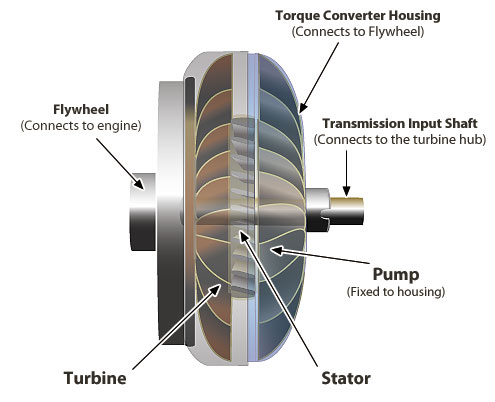
Torque Converter
Gear selection in automatic transmissions depends on many operational conditions, such as vehicle speed, engine speed, performance mode (where fitted) selected as well as driver assist systems such as traction control, stability control, automatic/autonomous braking and cruise control.
Provided all necessary conditions are met, and there is agreement between the Engine Management and Transmission Control systems, pressurized transmission fluid is automatically channelled to mechanisms that drive sets of planetary gears and clutches, which are roughly analogous to the gear ratios found in in this type of transmission.
Rotational energy is provided by a torque converter, a mechanism consisting of two freely rotating parts. One half is attached to the engine and the other to the transmission input shaft. The two halves of the converter are positioned very closely together. The fluid that circulates between them is influenced by the rotational energy of the engine which in turn impacts the transmission side of the converter. Torque is transferred from the engine to the transmission thanks to the shearing strength of fluid.
Torque Converter
In older automatic transmissions, the shifting action was accomplished by internal fluid pressures overcoming spring tension – closing one circuit before opening another. This control system produced harsh, jerky shifting. Modern systems moderate the action of the controlling valve shuttles, providing almost seamless shifting.

Advantages

  • Very easy to use
  • Provides a comfortable driving experience
  • Modern automatic transmissions match manual transmissions in terms of performance and fuel economy

Disadvantages

  • Complex and prone to failures, malfunctions, and unsatisfactory performance due to a variety of possible issues, some of which are unrelated to it itself
  • More expensive than a manual transmission to maintain over a vehicle’s lifetime
  • Expensive to repair. Replacement is often the more cost effective option
  • Unsuitable for use in off-road environments because it cannot provide engine braking

Semi-Automatic Transmissions

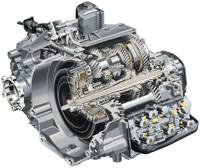
Dual Clutch Transmission
Also known as an “automatic manual” or “clutchless manual” transmission, the simplest way to describe this type is to call it a hybrid between a fully automatic and manual transmission.
Similar to a manual transmission, gears are changed via a simple shifter or paddles located behind the steering wheel. However, there is no need to operate a clutch pedal. Processors, sensors, pneumatics and actuators are all used to “automatically” shift the gears once the drive has signalled the change.
Paddle Shifter
The basic principles of shifting mechanical gears in a semi-automatic fashion have been in use on heavy commercial vehicles for many years. The latest and best designs provide lightning-fast, almost undetectable gearshifts.
The design of these systems varies, but all semi-automatic transmissions rely on microprocessors to control the changing of mechanical gear ratios with the help of electrically operated actuators and servos. These transmissions were limited to high-end supercars at first due to their high cost, but an increasing number of manufacturers are fitting them to mid-range cars.
Dual clutch systems employ two clutches, one controlling gearshifts in the even numbered gears and, anther that controls the odd numbered gears and reverse. This arrangement does not interrupt the power flow from the engine. The driver still has to initiate a gearshift via a shifter or paddles located behind the steering wheel, but there is no need for the driver to operate a clutch.

Advantages

  • Smoother shifting/driving experience
  • No energy losses due to slippage in torque converters, or during the time lag of manual shifts

Disadvantages

  • Complex and prone to failures, malfunctions, and unsatisfactory performance due to a variety of possible issues, some of which are unrelated to the transmission itself
  • More expensive to maintain than a manual transmission
  • Very expensive to repair. Replacement is often the more cost effective option

Continuously Variable Transmissions (CVT)

CVT
CVT
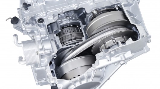
Unlike the others on this page, this transmission doesn’t use gears as its means of producing various vehicle speeds at different engine speeds. Instead of gears, the system relies on a rubber or metal belt running over pulleys that can vary their effective diameters. To keep the belt at its optimum tension, one pulley will increase its effective diameter, while the other decreases its effective diameter by exactly the same amount. This action is exactly analogous to the effect produced when gears of different diameters are engaged.

“Gear” Selection

Since one pulley is driven by the engine and the other is connected to the drive shaft, an infinite number of ratios can be produced. This enables it to always run at the most efficient speed, regardless of the load placed on it. Microprocessor-controlled sensors quantify load variations and by adjusting both pulleys, the optimum operating speed for the engine can be maintained without any input from the driver.

Advantages

  • Constant, stepless acceleration throughout the engine’s optimum operating range
  • Provides a comfortable ride by eliminating “shift shock”
  • Better fuel efficiency
  • Faster response to changing driving conditions such as variations in throttle and engine speed
  • Eliminates energy losses associated with torque converters. Bottom of Form

Disadvantages

  • Unsuitable for use in off-road environments because of limited torque-handling ability.
  • Cannot provide engine braking

Friday, 12 August 2016

ABS & EBD (Advanced braking system)


ABS (Anti-Lock Braking System)

As we know a vehicle moves due to the frictional force between the tyre and road. When we apply brakes, the brakes apply a torque in the opposite direction as that of friction and the wheel gradually comes to rest. This is how normal brakes work.
Now, whenever we are traveling on smooth surfaces like snow the friction coefficient is low and hence less frictional force. When a brake is applied in these conditions or even when you brake hard on a regular surface the amount of torque is so high that the vehicle's wheels stop rotating and start sliding. This is known as locking of wheels. Unless you are a skilled drifter this is potentially a dangerous situation as you don't have control over the wheels. (Experienced it firsthand a few months ago.)

So here comes the use of ABS. The function of abs is to prevent the wheels from locking even under very hard braking or on surfaces with low friction like snow, wet roads.

A typical ABS consists of the following parts
1. ECU
2. Four sensors for monitoring wheel speed
3. A pair of valves in each brake unit.

The ECU monitors the speed of each wheel.
If it detects that any wheel rotating at a slower speed than others (this indicates an imminent wheel lock) it redirects the valves to reduce brake pressure. Conversely if it detects a wheel faster than the others it instructs the valves to increase brake pressure. All of this helps us maintain control of our car even in extreme situations.


EBD (Electronic Brake Force Distribution System)
                          

EBD is basically a subsystem of ABS and it always works in conjunction with an ABS system. There main job of EBD is to optimise brake force on each wheel individually so to get maximum breaking power without losing control. It can alter braking pressure on each wheel individually depending on the conditions and weight distribution of the vehicle at that moment.