Search This Blog

Saturday, 13 August 2016

PROCESS OF TAPE CASTING

Tape casting is a casting process used in the manufacture of ceramic tapes from ceramic slurry.
      
During the Tape Casting process the slurry passes beneath the knife edge as the carrier surface advances along a supporting table. The solvents evaporate to leave a relatively dense flexible sheet or ceramic tape that may be stored on rolls or stripped from the carrier in a continuous process.The Tape Casting process involves the casting the slurry onto a flat moving carrier surface. The slurry usually consists of a ceramic powder with the appropriate additions of solvents plasticisers and binders. The ceramic tape produced can be used for a variety of purposes, including the manufacture of electronic components such as ceramic capacitors.Hope the above diagram makes you understand easier.

YOUTUBE CHANNEL

Hello everyone,I am glad to visit my new channel.Hope you all like it and am ready to give you the 3D modelling tutorials in solidworks.Visit my channel and give your comments

https://www.youtube.com/channel/UCn5xjVEG3A7-uApkQkkApLg

GEAR MECHANISM

Manual Transmissions

manual-transmission
As the name suggests, the selection of gear ratios on manual transmissions is accomplished by manually shifting a gear selector mechanism that disengages one gear and selects another. Most modern types of this transmissions have five or six forward (and one reverse) gears.
This type of transmission is connected to the engine via a clutch, which if disengaged (by pressing the foot pedal or hand lever), removes torque from the system. With the clutch engaged, power is delivered to the transmission through an input shaft that is separated from the primary cluster, and which can rotate at a different speed to the cluster. The cluster is comprised of gears that can be moved to either engage, or disengage from fixed gears on the secondary shaft, which is normally located below the cluster gears, and supported by roller bearings in its casing.

Gear Selection

The input shaft has only one gear that engages with a gear on the secondary shaft. When it is running and the clutch engaged, the transmission is said to be in “Neutral”. No gears on the primary are engaged with gears on the secondary shaft.
When shifting into first gear (for example), the gear on the primary shaft is slowed down by a synchronisation mechanism, and aligned with a gear on the secondary shaft. The current gear is always disengaged before the next one is engaged.  When the clutch is re-engaged, rotational energy is transferred from the transmission to the axle(s) by the drivetrain.
                           Manual Gear Selection
By using progressively smaller ratios, the speed of the vehicle can be maintained or increased using less power from the engine.

Advantages

  • Extremely robust, and can handle high torque loads.
  • Very reliable, and relatively easy to service, maintain, and repair.
  • The solid link between driving wheels and the engine provided by this transmissions provide a valuable driving aid to drivers in the off-road environment, by allowing the use of engine braking while descending slippery slopes where the use of ABS brakes could be dangerous.
  • Cheapest to repair

Disadvantages

  • Learning curve – can be difficult to operate for drivers who are accustomed to automatic

Fully Automatic Transmissions

automatic-transmission
In an automatic transmission, the hydraulically operated control systems are managed electronically by the vehicle’s computer instead of the clutch and gear stick. All the driver has to do is shift the selector from Park (P) or Neutral (N), into Drive (D), and the gear shifting will take place automatically and smoothly, without any additional input from the driver under normal driving conditions.

Gear Selection

Torque Converter
Gear selection in automatic transmissions depends on many operational conditions, such as vehicle speed, engine speed, performance mode (where fitted) selected as well as driver assist systems such as traction control, stability control, automatic/autonomous braking and cruise control.
Provided all necessary conditions are met, and there is agreement between the Engine Management and Transmission Control systems, pressurized transmission fluid is automatically channelled to mechanisms that drive sets of planetary gears and clutches, which are roughly analogous to the gear ratios found in in this type of transmission.
Rotational energy is provided by a torque converter, a mechanism consisting of two freely rotating parts. One half is attached to the engine and the other to the transmission input shaft. The two halves of the converter are positioned very closely together. The fluid that circulates between them is influenced by the rotational energy of the engine which in turn impacts the transmission side of the converter. Torque is transferred from the engine to the transmission thanks to the shearing strength of fluid.
Torque Converter
In older automatic transmissions, the shifting action was accomplished by internal fluid pressures overcoming spring tension – closing one circuit before opening another. This control system produced harsh, jerky shifting. Modern systems moderate the action of the controlling valve shuttles, providing almost seamless shifting.

Advantages

  • Very easy to use
  • Provides a comfortable driving experience
  • Modern automatic transmissions match manual transmissions in terms of performance and fuel economy

Disadvantages

  • Complex and prone to failures, malfunctions, and unsatisfactory performance due to a variety of possible issues, some of which are unrelated to it itself
  • More expensive than a manual transmission to maintain over a vehicle’s lifetime
  • Expensive to repair. Replacement is often the more cost effective option
  • Unsuitable for use in off-road environments because it cannot provide engine braking

Semi-Automatic Transmissions

Dual Clutch Transmission
Also known as an “automatic manual” or “clutchless manual” transmission, the simplest way to describe this type is to call it a hybrid between a fully automatic and manual transmission.
Similar to a manual transmission, gears are changed via a simple shifter or paddles located behind the steering wheel. However, there is no need to operate a clutch pedal. Processors, sensors, pneumatics and actuators are all used to “automatically” shift the gears once the drive has signalled the change.
Paddle Shifter
The basic principles of shifting mechanical gears in a semi-automatic fashion have been in use on heavy commercial vehicles for many years. The latest and best designs provide lightning-fast, almost undetectable gearshifts.
The design of these systems varies, but all semi-automatic transmissions rely on microprocessors to control the changing of mechanical gear ratios with the help of electrically operated actuators and servos. These transmissions were limited to high-end supercars at first due to their high cost, but an increasing number of manufacturers are fitting them to mid-range cars.
Dual clutch systems employ two clutches, one controlling gearshifts in the even numbered gears and, anther that controls the odd numbered gears and reverse. This arrangement does not interrupt the power flow from the engine. The driver still has to initiate a gearshift via a shifter or paddles located behind the steering wheel, but there is no need for the driver to operate a clutch.

Advantages

  • Smoother shifting/driving experience
  • No energy losses due to slippage in torque converters, or during the time lag of manual shifts

Disadvantages

  • Complex and prone to failures, malfunctions, and unsatisfactory performance due to a variety of possible issues, some of which are unrelated to the transmission itself
  • More expensive to maintain than a manual transmission
  • Very expensive to repair. Replacement is often the more cost effective option

Continuously Variable Transmissions (CVT)

CVT
CVT
Unlike the others on this page, this transmission doesn’t use gears as its means of producing various vehicle speeds at different engine speeds. Instead of gears, the system relies on a rubber or metal belt running over pulleys that can vary their effective diameters. To keep the belt at its optimum tension, one pulley will increase its effective diameter, while the other decreases its effective diameter by exactly the same amount. This action is exactly analogous to the effect produced when gears of different diameters are engaged.

“Gear” Selection

Since one pulley is driven by the engine and the other is connected to the drive shaft, an infinite number of ratios can be produced. This enables it to always run at the most efficient speed, regardless of the load placed on it. Microprocessor-controlled sensors quantify load variations and by adjusting both pulleys, the optimum operating speed for the engine can be maintained without any input from the driver.

Advantages

  • Constant, stepless acceleration throughout the engine’s optimum operating range
  • Provides a comfortable ride by eliminating “shift shock”
  • Better fuel efficiency
  • Faster response to changing driving conditions such as variations in throttle and engine speed
  • Eliminates energy losses associated with torque converters. Bottom of Form

Disadvantages

  • Unsuitable for use in off-road environments because of limited torque-handling ability.
  • Cannot provide engine braking

Friday, 12 August 2016

ABS & EBD (Advanced braking system)


ABS (Anti-Lock Braking System)

As we know a vehicle moves due to the frictional force between the tyre and road. When we apply brakes, the brakes apply a torque in the opposite direction as that of friction and the wheel gradually comes to rest. This is how normal brakes work.
Now, whenever we are traveling on smooth surfaces like snow the friction coefficient is low and hence less frictional force. When a brake is applied in these conditions or even when you brake hard on a regular surface the amount of torque is so high that the vehicle's wheels stop rotating and start sliding. This is known as locking of wheels. Unless you are a skilled drifter this is potentially a dangerous situation as you don't have control over the wheels. (Experienced it firsthand a few months ago.)

So here comes the use of ABS. The function of abs is to prevent the wheels from locking even under very hard braking or on surfaces with low friction like snow, wet roads.

A typical ABS consists of the following parts
1. ECU
2. Four sensors for monitoring wheel speed
3. A pair of valves in each brake unit.

The ECU monitors the speed of each wheel.
If it detects that any wheel rotating at a slower speed than others (this indicates an imminent wheel lock) it redirects the valves to reduce brake pressure. Conversely if it detects a wheel faster than the others it instructs the valves to increase brake pressure. All of this helps us maintain control of our car even in extreme situations.


EBD (Electronic Brake Force Distribution System)
                          

EBD is basically a subsystem of ABS and it always works in conjunction with an ABS system. There main job of EBD is to optimise brake force on each wheel individually so to get maximum breaking power without losing control. It can alter braking pressure on each wheel individually depending on the conditions and weight distribution of the vehicle at that moment.

This is how metal balls of steel be manufactured.

MANUFACTURING OF METAL BALLS

Metal balls start as a wire. The wire is sheared to give a pellet with a length approximately the size of the desired ball outer diameter (OD). This pellet is then headed into a rough spherical shape. Next, the balls are then fed into a machine that de-flashes them. The machine does this by feeding the balls between two heavy cast iron or hardened steel plates, called rill plates. One of the plates is held stationary while the other rotates. The top plate has an opening to allow balls to enter and exit the rill plates. These plates have fine circumferential grooves that the balls track in. The balls are run through the machine long enough so that each ball passes through many of these grooves, which ensures each ball is the same size, even if a particular groove is out of specification. The controllable machine variables are the amount of pressure applied, the speed of the plates, and how long the balls are left in the machine.
During the operation coolant is pumped between the rill plates because the high pressure between the plates and friction creates considerable heat. The high pressure applied to the balls also induces cold working, which strengthens the balls.
Sometimes the balls are then run through a soft grinding process afterward to improve precision. This is done in the same type of machine, but the rill plates are replaced with grinding stones.
If the balls are steel they are then heat treated. After heat treatment they are descaled to remove any residue or by-products.
The balls are then hard ground. They are ground in the same type of machine as used before, but either an abrasive is introduced into coolant or the rotating plate is replaced with a very hard fine-grain grinding wheel. This step can get the balls within ±0.0001 in (0.0025 mm). If the balls need more precision then they are lapped, again in the same type of machine. However, this time the rill plates are made of a softer material, usually cast iron, less pressure is applied, the plate is rotated slowly. This step is what gives bearing balls their shiny appearance and can bring the balls between grades 10 and 48.
If even more precision is needed then proprietary chemical and mechanical processes are usually used.
The inspection of bearing balls was one of the case studies in Frederick Winslow Taylor's classic Principles of Scientific Management.

Thursday, 11 August 2016

Formula behind Rubik's cube.

THERE BE A SCIENCE BEHIND RUBIK'S CUBE IS TO CONCENTRATE YOUR MIND AND DO IT...PURE MECHANICAL SCIENCE


The Solution step by step

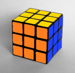
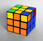
1. White cross


Bad white cross

Good white cross
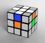
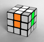
Let’s begin with the white face. First we have to make a white cross paying attention to the colour of the center pieces. This step is quite intuitive, you can do it for sure with a little practice. Just move the white edges to their places not messing up the ones already fixed.
If you have difficulties, you can get a little more help with animated algorithms about solving the white cross on the Rubik’s Cube clicking here.

2. White corners

In this step we have to arrange all the white corner pieces, so we finish the first face. This step is still intuitive, you can do it without learning a single algorithm. If you don’t have patience I’ll give you some clues. Move the white corner under the spot where it’s supposed to be, then do one of the three algorithms according to the orientation of the piece, aka. in which direction the white sticker is facing. If the white corner piece is where it belongs but turned wrong then first you have to pop it out.
For more details about the solution of the white corners here.

White face solved

R’ D D R D R’ D’ R

F D F’

R’ D’ R

3. Second layer


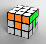
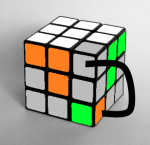
Until this point the procedure was intuitive, from now on we have to use algorithms. We can turn the white face to the bottom and in this step we will complete the first two layers (F2L). There are two algorithms we use and they are symmetric. They’re called the F2L Right and F2L Left algorithms. These algorithms insert the Up-Front edge piece from the top layer in the middle layer not messing up the already solved white face.
If an edge piece is on its place in the second layer orienting wrong then we have to apply the algorithm twice. First we must pop it out inserting another one in its place.

F2L solved

Wrong orientation

Right: U R U’ R’ U’ F’ U F

Left: U’ L’ U L U F U’ F’

4. Yellow cross


Yellow cross on the top
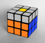
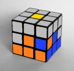
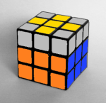
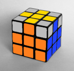
Now make a yellow cross on the top of the cube. It doesn’t matter if the pieces are not on their final places so we don’t have to pay attention to the colours of the sides now. Just make a yellow cross on the top, we will swap them in the next step.
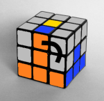
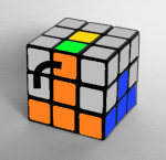
We can get three possible patterns on the top. We can get from one to the other pattern with a single algorithm as seen on the image: F R U R’ U’ F’
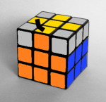
  1. If you have a yellow “L” shape you’ll have to apply the algorithm twice, holding the cube in your hands as seen on the first image below.
  2. In case of a horizontal line you just have to make the permutation once.
solve the yellow cross

5. Yellow edges


  Yellow edges done

Switch the edges
After making the yellow cross on the top of the cube you have to put the yellow edge pieces on their right places where they belong. Switch the front and left yellow edges with the following algorithm:
R U R’ U R U U R’ U
There are situations when you have to apply this algorithm more than once.

6. Yellow corners on their places


Switch three corner pieces
Only the last layer corner pieces are left. First we have to get them to the right spot, so don’t worry about the orientation in this step.
Find a piece which is already on the right place, move it to the right-front-top corner then apply the following algorithm to switch (rotate) the three wrong pieces:
U R U’ L’ U R’ U’ L
Do this twice to do an inverse rotation of the pieces. If none of the yellow corners is on the right place then do the algorithm once so one of them will go to the right spot.


7. Orient Yellow corners


The cube is solved

Orient the corner pieces
Now all the pieces are on their right places you just have to orient the yellow corner pieces.
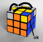
Hold the cube in your hand so the piece you want to orient is on the front-right-top corner, then do the R’ D’ R D algorithm twice or four times until that specific piece is oriented well. It seems like you messed up the whole cube but don’t worry, it will be all right when all the corner pieces are oriented.
After that with a U’ turn move another yellow piece you want to orient to the front-right-top corner of the cube and doR’ D’ R D again while this specific piece is ok. Be careful not to move the two bottom layers between the algorithms and never rotate the whole cube!

Wednesday, 10 August 2016

STIRLING ENGINE WITH FRESNEL LENS FOR POWER GENERATION

INTRODUCTION
              A Stirling engine is a heat engine operating by cyclic compression and expansion of air or other gas, the working fluid, at different temperature levels such that there is a net conversion of heat energy to mechanical work. The cycle is reversible, meaning that if supplied with mechanical power, it can function as a heat pump for heating or cooling, and even for cryogenic cooling.

           The cycle is defined as a closed regenerative cycle with a gaseous working fluid. "Closed cycle" means the working fluid is permanently contained within the thermodynamic system. This also categorizes the engine device as an external heat engine. "Regenerative" refers to the use of an internal heat exchanger called a regenerator which increases the device's thermal efficiency.

            Solar energy is used to heating the input air of the cylinder. The Fresnel lens are focused the solar rays into the hot end cylinder air. So the air pressure is increased and expands the piston to produce mechanical energy. This process is cyclic and the power producing is continuously.


ADVANTAGES
Ø  They can be built to run quietly and without an air supply & they start easily (albeit slowly, after warm up)

Ø  Stirling engines can run directly on any available heat source

Ø  Waste heat is easily harvested

DISADVANTAGES

Ø  Typically these material requirements substantially increase the cost of the engine.
                             
Ø  A Stirling engine cannot start instantly; it literally needs to "warm up". This is true of all external combustion engines.

APPLICATIONS

Ø  It is probably there that the Stirling engine will develop more power & this will be a way to
  make electricity, heating of home and to produce domestic hot water.


Ø  The residential electric power represents now about 8% of total production.